Just 'Cuz Robotics
Long All-In-One PD Board V2.1
Long All-In-One PD Board V2.1
Share
Couldn't load pickup availability
Smaller, Lighter, More Durable, and Cheaper than the old AIO!
Switch, BEC, and power LED All In One Product! Save Time, Money, Space and More. 3D model access is included here! And a quick reference user guide can be found here. (will be updated for long AIO soon)
Just 'Cuz Robotics has designed a helpful, functional, compact, lightweight PCB to make wiring your bots, simple, easy, and less error-prone. In addition, this version incorporates a screw power switch, 5V BEC, power indicator LED, and a convenient set of output pads for connecting a receiver.
Compared to the old more square shaped AIO V1 series, this version has a few major changes:
- Instead of a more expensive and bulky DC-DC switching regulator, this board uses a much smaller linear regulator. This same BEC is used on the Motherboard and has proven reliable in >100 SSP kits and 100s of fights on 3S.
- BEC can only supply 5V @ 100mA, or a bit more with lower input voltage (tested at 18V for 30 minutes at 100mA max). The AIO V1.2 - V1.6 can supply 500mA, so if you are powering more than just a receiver it may be a better choice.
- Uses two larger mounting screw holes (up to #6 plastite screws!) on the sides of the board instead of 4 more randomly placed ones.
- This board is much longer but thinner and lighter, and easily mounts with connectors facing either direction compared to the switch screw.
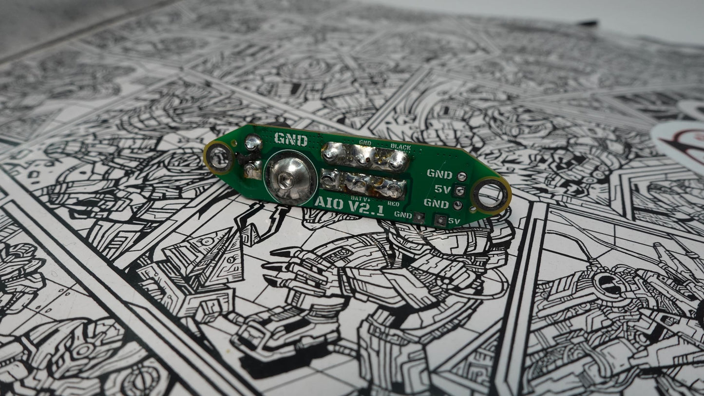
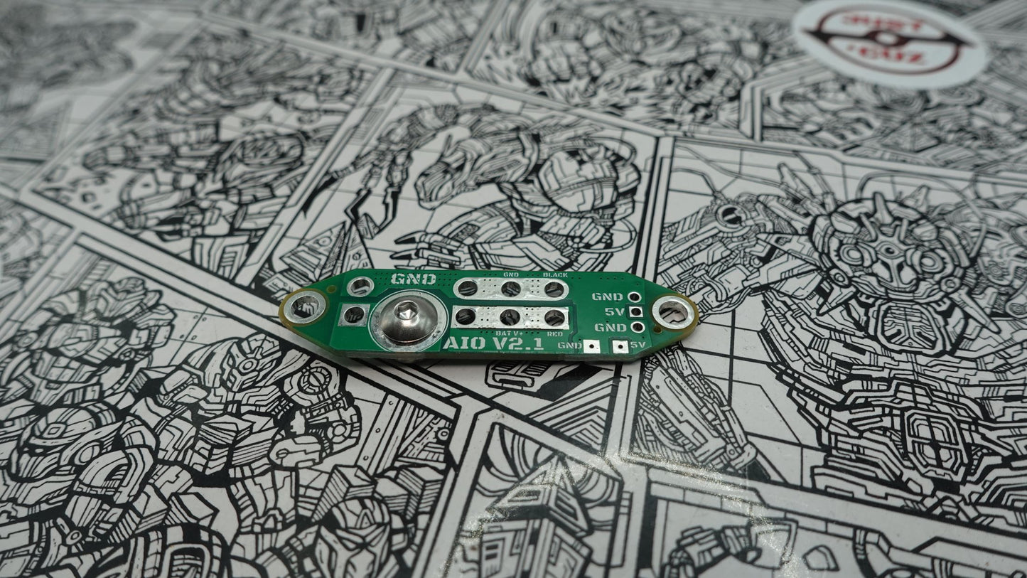
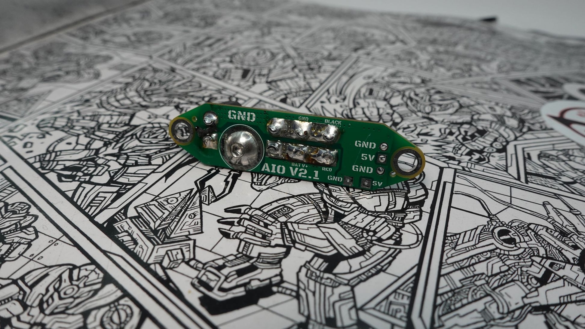
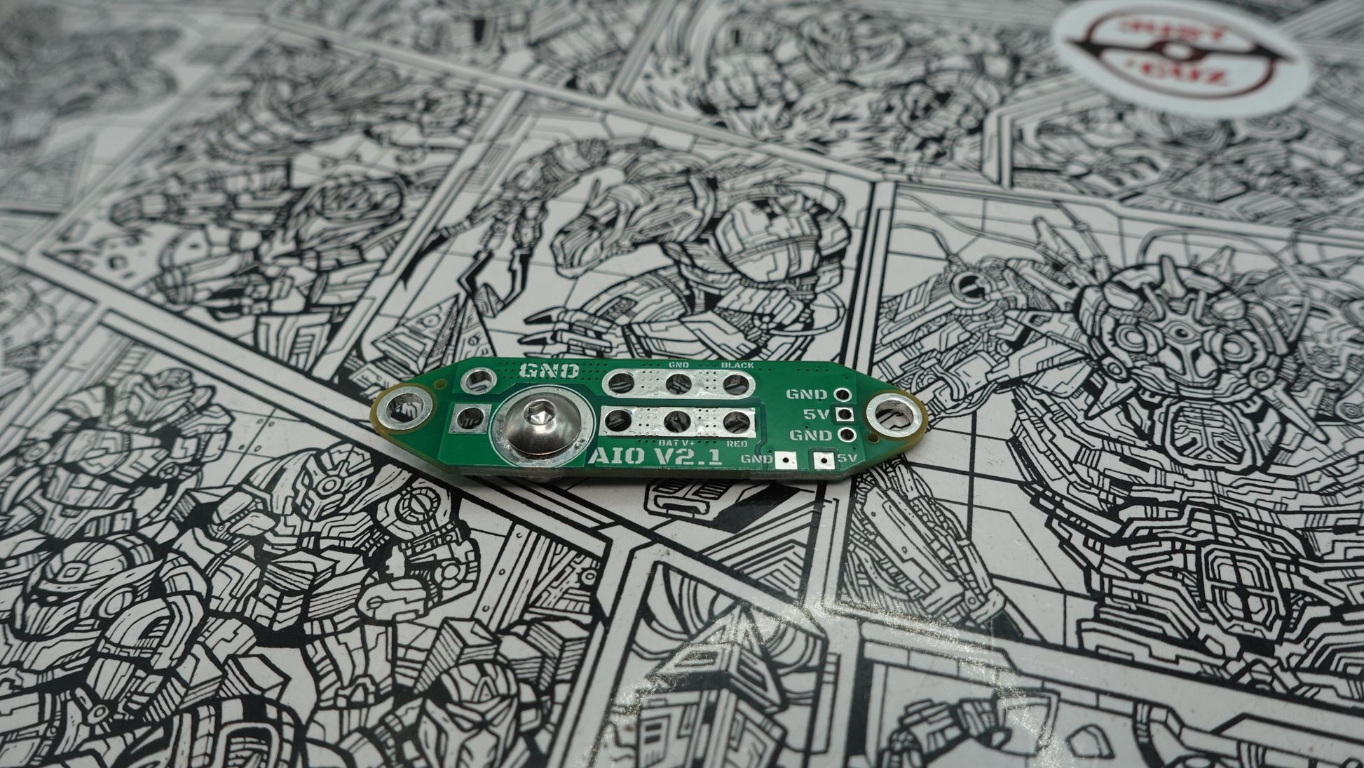
WARNING: The bottom of the board has exposed copper regions that, if in contact with a conductive surface, can short circuit. Do not secure this board directly to a conductive metal plate, and ensure that an insulative spacer (electrical tape, hot glue, 3D printed plastic cover) is used before connecting a battery if resting on a conductive surface. These regions are exposed to allow easy soldering to the underside of the board, but they are separated for a reason!
What's included per purchase:
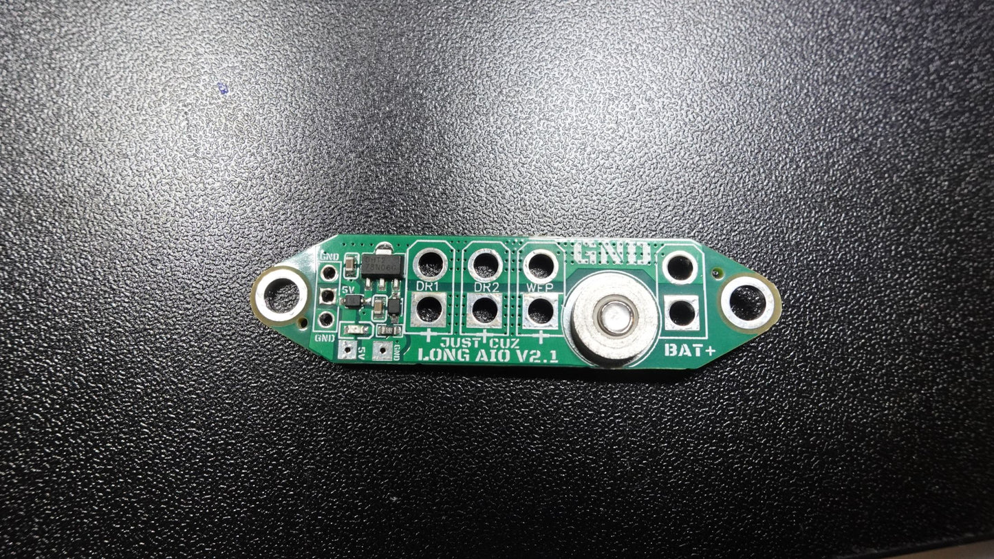
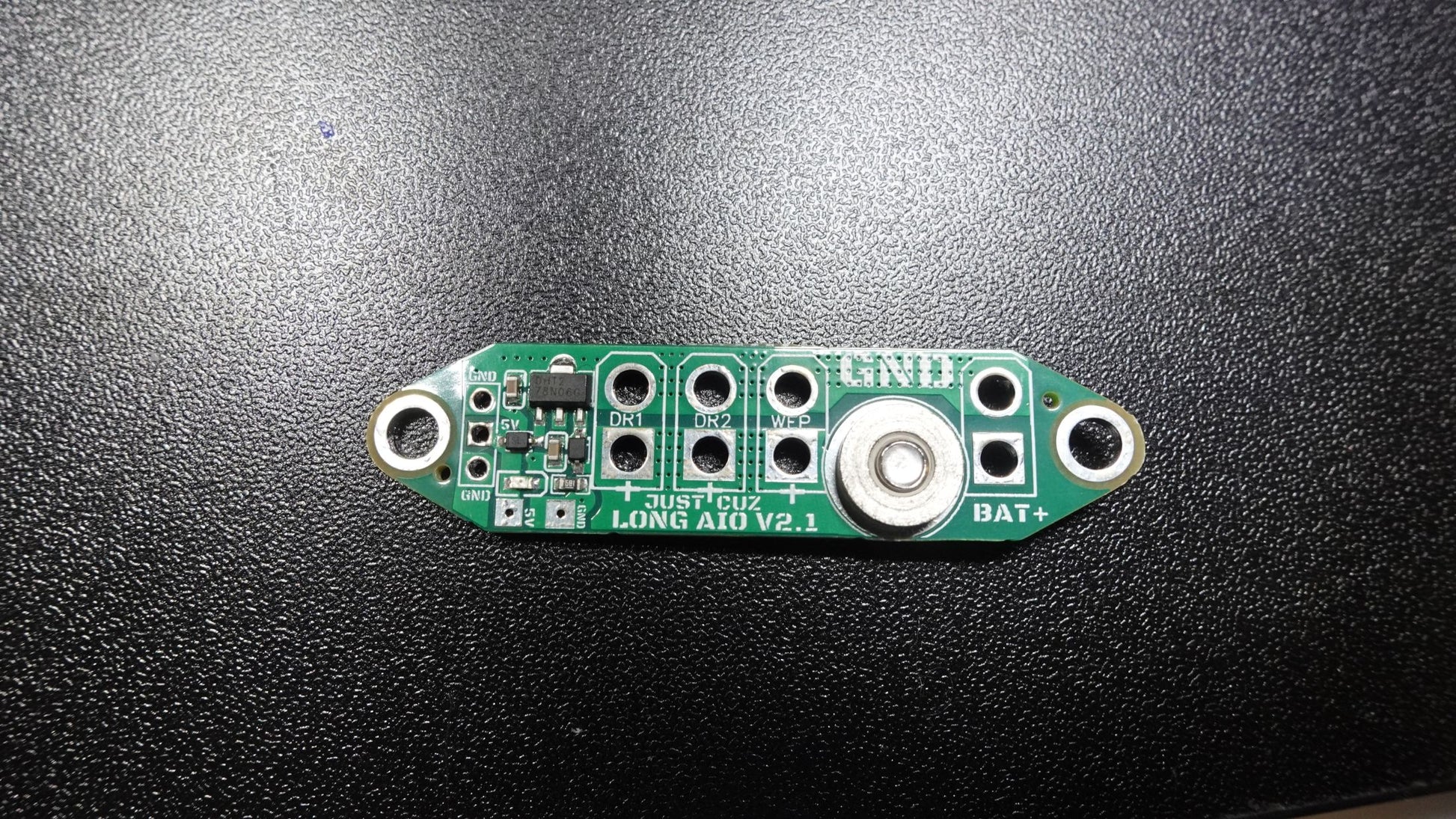
- One (1) board with 5V regulator, LED, and related SMD components preassembled
- One (1) Tin plated steel #8-32 press insert nut, pressed into the power switch hole
- One (1) #8-32 Button Head Screw for the power switch (3/32" hex drive just like Fingertech switches use!)
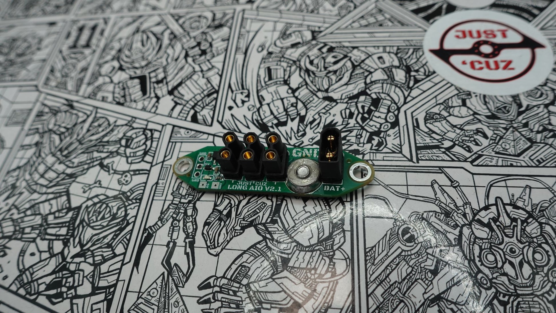
Recommended Addons: 4 pairs XT30U Connectors and Servo Jumper Cable
Features
Features:
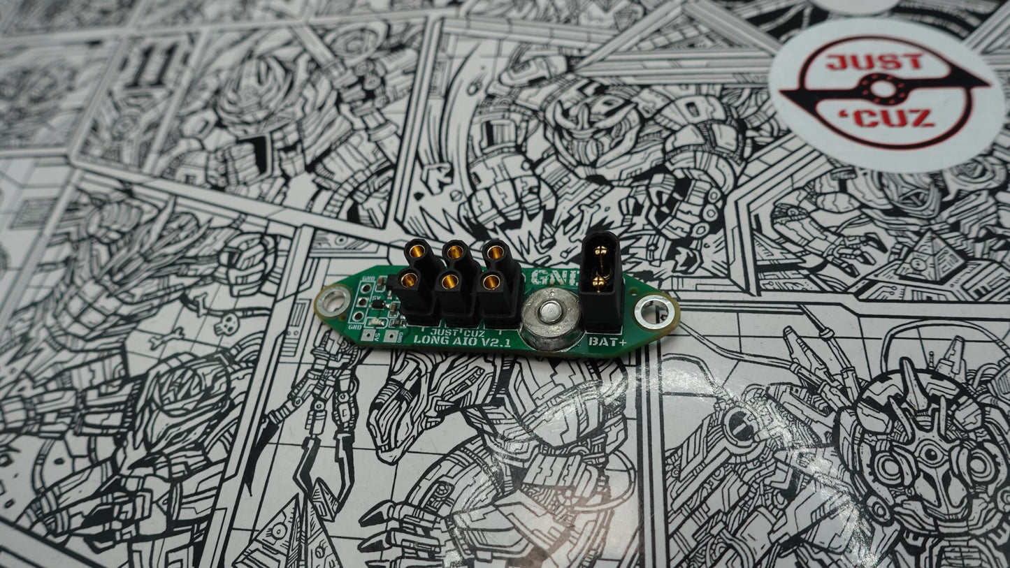
- Convenient mounting points for up to four XT30 or XT30U connectors! Battery, Weapon, and two drive sides (I recommend using Male for Battery and Female for others on the board)
- Clearly marked orientation for connectors to avoid reverse polarity ruining your parts
- Use any connector or combination of direct soldering and connectors
- 5V BEC capable of handling input voltages of 6.5V to 36V (2S to 6S LiPo recommended) to power a receiver or other 5V devices up to 100mA
- (NOTE: a precharge circuit should be used above 3S, and additional solder on top of the circular pad under the screw head is recommended)
- Built-in screw switch to disconnect battery voltage from all devices (tested at 32A for 3.5 minutes, 50A+ for 30 seconds)
- Convenient bright power LED for power indication
- 3-pin servo connector compatible header for RX connection (get servo extension cables female-female)
- When the screw is tightened, this connects battery positive to all other connector positive terminals, sends 5V power to the receiver header, and turns on the power LED. (SW pad to the top circle pad must be shorted with 18AWG or larger wire for testing/use without a switch/link.)
- Massive copper pads for increased current-carrying and heat dissipation
- Can connect as many other devices as you wish to the copper pads under the board - no need to use just four!
- No need for a messy wire 'squid' to wire all your ESCs!
- Convenient M3/#6 mounting screw holes to hold down the board or attach a cover
- Size is about 57 mm by 14.4 mm, 50mm between mounting holes
- Weight of just 8.4 grams assembled! 4.2g with no connectors.
- Clear labels for all components and pins for easy assembly and troubleshooting
- 3D model access included here
Safety
Warning: combat robots are not toys! They are extremely dangerous. Click here for a safety video.
Operation with a battery at a higher voltage than 6S, or drawing too much current from the BEC without added cooling, may result in damage to the 5V regulator. It can be replaced by an off-the-shelf part, Contact Us for more info.
While this PCB is designed to safely operate inside a combat robot, it may get very hot. Touching it during, or shortly after operation, can result in serious burns.
In the unlikely case where you have difficulty turning off the switch while it is hot, waiting 30-60 seconds for it to cool should resolve the issue.
NOTE: I have gotten word the switch can be hard to turn on if the board is flat against a baseplate without a proper spacer. This is because the screw is a bit longer than needed. Sanding off about 1/32 inch from the threaded side should fix this.
Testing a robot with an active spinning weapon should never be done while maintaining a line of sight with the robot. Ideally, you should be testing inside an enclosed box or arena with at least 1/4" thick polycarbonate windows or top to see through, and 1/2” or thicker plywood or MDF construction. Operation (Including testing) outside of a suitable arena or test box could cause serious injury. By purchasing this product you acknowledge that you are responsible for the safe use of this product and that Team Just ‘Cuz Robotics or its employees are not liable for any injuries or damages.
Mistakenly shorted this Long AIO PCB Board yet still works. This board is really awesome!!!
I had been struggling with getting multiple power wires constantly connected in a toggle connector. If I touched the wires just right one component would lose power. I decided to give the all in one PCB board a try to see if that would help. Not only was I able to have secure connections it I got rid of my standalone power switch with harness and my BEC! Things are much more organized and takes up a lot less space. This is differently a great option to simplify your robots wiring and make it more robust
I initially didn’t have the highest review of this board, I had two main issues that were immediately resolved by Seth. You MUST solder the nut to the top side of the board for it to work properly. The initial CAD file for the board was also incorrect, but has been corrected since. In battle this thing was bulletproof!
